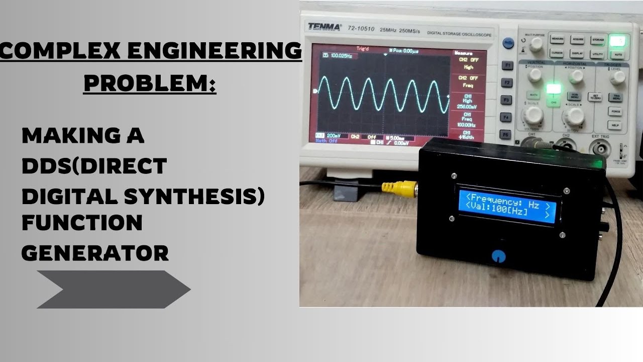
𝐎𝐯𝐞𝐫𝐜𝐨𝐦𝐢𝐧𝐠 𝐄𝐧𝐠𝐢𝐧𝐞𝐞𝐫𝐢𝐧𝐠 𝐂𝐡𝐚𝐥𝐥𝐞𝐧𝐠𝐞𝐬:𝐃𝐞𝐬𝐢𝐠𝐧𝐢𝐧𝐠 𝐚 𝐃𝐃𝐒 𝐅𝐮𝐧𝐜𝐭𝐢𝐨𝐧 𝐆𝐞𝐧𝐞𝐫𝐚𝐭𝐨𝐫
In my Embedded Systems course, my team tackled an exciting challenge: designing a DDS (Direct Digital Synthesis) function generator. DDS is a digital method for generating precise waveforms.A DDS (Direct Digital Synthesis) function generator is an electronic device or system used to generate precise and stable waveforms of various types (such as sine, square, triangular, and sawtooth waves) at a wide range of frequencies. It is a versatile tool commonly used in signal processing, telecommunications, and instrumentation.
𝐊𝐞𝐲 𝐂𝐨𝐦𝐩𝐨𝐧𝐞𝐧𝐭: 𝐓𝐡𝐞 𝐀𝐃𝟵𝟴𝟯𝟯 𝐈𝐂:
We based our design around the AD9833 IC—a low-power, programmable waveform generator. This powerful IC can generate waveforms across three modes:
𝗠𝗼𝗱𝗲 𝟭: Sine Wave
𝗠𝗼𝗱𝗲 𝟮: Triangle Wave
𝗠𝗼𝗱𝗲 𝟯: Square Wave
With an output frequency range up to 12.5 MHz and a power output of 12.65 mW.The input voltage range is 2.3V to 5V, peak-to-peak output voltage of 0.6V (for a 5V input) and 0.4V (for a 3.3V input).
𝐀𝐦𝐩𝐥𝐢𝐟𝐲𝐢𝐧𝐠 𝐭𝐡𝐞 𝐒𝐢𝐠𝐧𝐚𝐥: 𝐋𝐌𝟳𝟰𝟭 𝐎𝐩-𝐀𝐦𝐩 𝐂𝐨𝐧𝐟𝐢𝐠𝐮𝐫𝐚𝐭𝐢𝐨𝐧:
The amplitude of ad9833 was low so we integrated opamp
𝗜𝗻𝘃𝗲𝗿𝘁𝗶𝗻𝗴 𝗖𝗼𝗻𝗳𝗶𝗴𝘂𝗿𝗮𝘁𝗶𝗼𝗻: The AD9833 output was connected to the inverting input (pin 2) of the LM741, with a 10K potentiometer on the non-inverting input (pin 3) to manage DC offset.The 10k potentiometer was configured as a voltage divider with ±12V across its ends, and the middle pin connected to pin 3 of the LM741 for DC offset control.
𝗙𝗲𝗲𝗱𝗯𝗮𝗰𝗸 𝗟𝗼𝗼𝗽: A 50K potentiometer in the feedback loop between pin 2 and pin 6 controlled the gain, following the formula -Rf/Rin.
𝗕𝗶𝗮𝘀𝗶𝗻𝗴: ±12V biasing voltages were applied to pins 4 and 7 of the LM741 to set the waveform's peak range and prevent clipping.
𝐏𝐮𝐬𝐡 𝐁𝐮𝐭𝐭𝐨𝐧 𝐈𝐧𝐭𝐞𝐠𝐫𝐚𝐭𝐢𝐨𝐧 𝐚𝐧𝐝 𝐂𝐨𝐧𝐭𝐫𝐨𝐥 𝐋𝐨𝐠𝐢𝐜:
We integrated four push buttons into our DDS function generator for user control:
𝐖𝐚𝐯𝐞𝐟𝐨𝐫𝐦 𝐒𝐞𝐥𝐞𝐜𝐭𝐢𝐨𝐧: The blue button on port C cycles through waveforms (sine, triangle, square) using the AD_SETMODE function.
𝐅𝐫𝐞𝐪𝐮𝐞𝐧𝐜𝐲 𝐑𝐚𝐧𝐠𝐞 𝐒𝐞𝐥𝐞𝐜𝐭𝐢𝐨𝐧: The second button toggles between frequency ranges (Hz, kHz, MHz) for precise output tuning.
𝐈𝐧𝐜𝐫𝐞𝐦𝐞𝐧𝐭/𝐃𝐞𝐜𝐫𝐞𝐦𝐞𝐧𝐭 𝐅𝐫𝐞𝐪𝐮𝐞𝐧𝐜𝐲: The third and fourth buttons adjust the frequency in steps of 10.
𝗣𝗿𝗼𝗴𝗿𝗮𝗺𝗺𝗶𝗻𝗴 𝘁𝗵𝗲 𝗔𝗗𝟵𝟴𝟯𝟯 𝗠𝗼𝗱𝘂𝗹𝗲:
The AD9833 IC was programmed via SPI communication using Embedded C. Arduino as the master and the AD9833 as the slave and configured as MOSI.
𝗪𝗮𝘃𝗲𝗳𝗼𝗿𝗺 𝗦𝗲𝗹𝗲𝗰𝘁𝗶𝗼𝗻 (𝗔𝗗_𝗦𝗘𝗧𝗠𝗢𝗗𝗘): This function sends a 16-bit hex code to the AD9833 to select the desired waveform.
𝗙𝗿𝗲𝗾𝘂𝗲𝗻𝗰𝘆 𝗖𝗼𝗻𝘁𝗿𝗼𝗹 (𝗔𝗗_𝗴𝗲𝘁𝗙𝗿𝗲𝗾𝘂𝗲𝗻𝗰𝘆): Frequency adjustment is achieved by sending a 28-bit data stream to the AD9833. The lower 14 bits and upper 14 bits are sent separately to ensure accurate frequency setting.
𝗣𝗵𝗮𝘀𝗲 𝗔𝗱𝗷𝘂𝘀𝘁𝗺𝗲𝗻𝘁 (𝗔𝗗_𝗦𝗘𝗧𝗣𝗛𝗔𝗦𝗘): This function manages the phase angle of the waveform, sending a 12-bit data stream to the AD9833.[ Ссылка ]


![Directed by Robert B. Weide [TEMPLATE]](https://s2.save4k.ru/pic/qzbtdclsJXw/mqdefault.jpg)